


Description
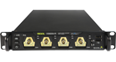
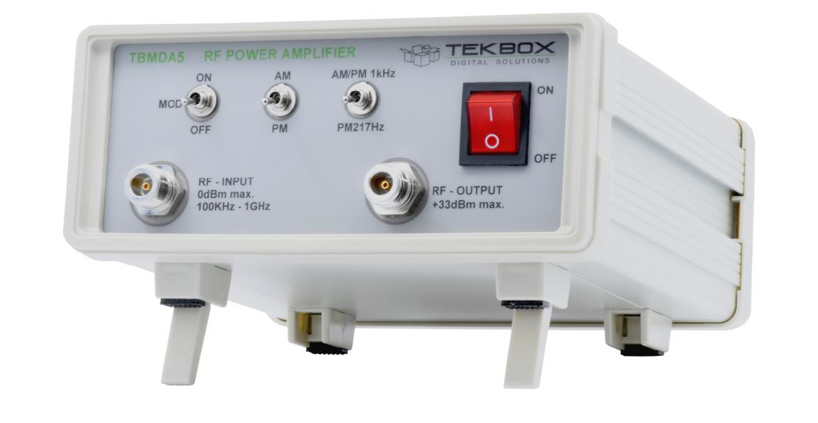
TBMDA5 Modulated Wideband Power Amplifier
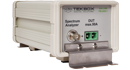
The TBMDA5 modulated amplifier provides the necessary power, bandwidth and modulation for conducted immunity testing using CDNs in the frequency range from 150 kHz to 400 MHz. It is designed to be driven by the tracking generator output of spectrum analyzers.
With a 1 dB compression point of up to 2.5W in the frequency range 150 kHz to 400 MHz it can generate test levels class 1 and class 2 according to ISO / EN 61000-4-6. A built in AM- modulator enables use of tracking generators as signal source.
The TBMDA5 has sufficient gain to achieve maximum output power with 0 dBm provided by a spectrum analyzer tracking generator.
Besides 1 kHz, 80% AM, the TBMDA5 provides built in modulation capability to generate 1 kHz, 50% duty cycle PM signals. In PM mode, the TBMDA5 can also generate a 217 Hz Signal with 12.5% duty cycle in order to simulate mobile phone TDMA noise.
Features:
- CW amplifier (modulation off)
- 1 kHz, 80% AM modulation
- 1 kHz, 50% duty cycle pulse modulation 217 Hz
- 12.5% duty cycle pulse modulation


Reviews
There are no reviews yet.