


EMC Precompliance Testing: Conducted Emissions
Electromagnetic Interference (EMI) can cause undesirable effects on electronic products. These effects can range from annoying glitches to rendering a product unusable.
In an effort to minimise these issues, countries have established standards and limits to products that are being sold within that market. This Electromagnetic Compatibility (EMC) testing is an integral part of product design and qualification for any electronics intended for sale within those markets.
In almost every case, these specifications contain limits on conducted and emitted radiation testing. Conducted emissions are those that propagate through the power line connecting the instrument (Equipment Under Test, or EUT here). Radiated emissions are those that are emitted into the area surrounding the EUT.
This note will briefly cover some common practices for conducted emission testing early in the design phase and we will cover the radiated emissions in another note.
A Word about Precompliance
For full qualification testing, a CISPR 16 qualified EMI Receiver and the proper setup must be used. This generally requires using a certified testing lab and special equipment that can be cost prohibitive for development and design tweaking.
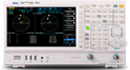
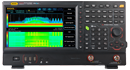
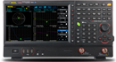
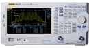
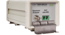
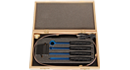
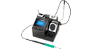
This note covers pre-compliance measurements using a Rigol DSA-815 Spectrum Analyser with the optional EMI Measurement Kit (Part Number DSA800-EMI).
While not fully providing fully compliant measurement data, pre-compliance testing can give you critical visibility into the design limitations of your design. You can find the sources of your EMI and try to limit their contributions before the fully compliant testing even begins.
Perhaps the best methodology is to perform a number of pre-compliance tests on a product using a number of physical configurations. Then, compare that data to the data collected in a fully compliant setup.
Using this “Golden Standard” comparison can give you confidence in your pre-compliance measurements and also give you insight into your testing deficiencies. Many of the differences may be systematic and accounted for by allowing for a bigger error cushion on the limits you are testing against.
Physical measurement setup
The more closely you can match a full compliance setup, the more closely your data will match with the lab. But, this isn’t always practical.
The following diagrams show the standard suggested electrical and physical setups for testing conducted emissions:
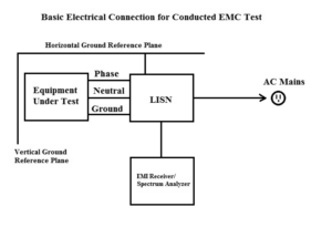
Figure 1: Electrical connections for Conducted EMC Testing.
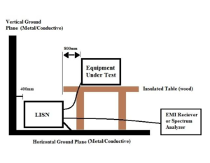
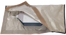
Figure 2: Physical connections for Conducted EMC Testing.
The key points:
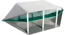
- The horizontal and vertical ground planes are typically sheets of metal with surface areas twice the dimensions of the Equipment-Under-Test.
- The horizontal and vertical ground planes should be electrically bonded to each other.
- Equipment placed on insulated table over the horizontal ground plane. No equipment or cabling should run below the equipment.
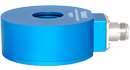
- LISN electrically bonded to the horizontal ground plane. LISN is short for Line Impedance Stabilization Network. Its job is to separate the AC Mains noise from the conducted noise being generated by the Equipment-Under- Test. Please select a LISN that has the proper voltage, current, and frequency ranges for your equipment-under-test.
- Do not coil cables. You want to minimise inductive loops by laying cabling out smoothly.
- The spectrum analyser should be placed some distance away from the horizontal ground plane. Typically, it is a few feet away.
Test Procedure
Once you have setup the EUT and bonded the LISN and ground planes, power on the DSA815 for at least 30 minutes to ensure stability and accuracy.
Configure Spectrum Analyser
- Enable the EMI filter by pressing BW/DET > Filter Type > EMI
- Set Resolution Bandwidth by pressing BW > RBW
NOTE: The resolution bandwidth is determined by the standard and specific device type you are testing. As an example, FCC subpart-15 specifies an RBW of 9kHz when testing from 150kHz to 30MHz.
You should consult the standards you are testing to for more information on the specifications governing your testing.
NOTE: Many specifications give limits and values in dBuV or V.
Optional: Set scale for volts by pressing AMPT > Units > V
NOTE: The DSA-815 has a pass/fail feature that will allow you to configure an upper limit line. This can be useful when evaluating the frequency scan respect to the limits set forth by the EMC standard you are testing to.
You can also save any limit lines to the internal storage, once it has been created. Simply configure the limit line on the instrument, press Storage > change File Type to Limit, and save the file.
Optional: Add an upper limit line by pressing Trace/ P/F > Pass/Fail > Switch ON > Setup > Upper > Edit and configure point 1 to have an X Axis start at 150kHz with an amplitude of 1mV.
Next, add a point 2 with start at 30MHz and an amplitude of 1mV. Set Connected to Yes for point 2.
This will connect point 1 and 2 with a purple line. This denotes the upper Pass/Fail line.
- Set detector type to Peak by pressing BW/Det > Type > Pos Peak
- Set the attenuator to 10dB by pressing AMPT > Input Atten > 10dB
- If the signal is unknown, adding significant external attenuation will minimise the likelihood of damage to the sensitive front end of the spectrum analyser.
NOTE: There are two reasons to add attenuation. The attenuator protects the input circuit from any unknown signals that could damage the input. It also serves as a convenient check on overloading after we check the background readings.
The DSA has protection circuitry, but there are transients that are too fast to protect against.
- Set frequency start, stop values set forth in the EMC Specifications that apply to the product. In this example, we are going to configure the instrument to sweep from 150kHz to 30MHz by pressing FREQ > Start and set to 150kHz. Then, press FREQ > Stop and set to 30MHz.
- Set the RBW to the value set forth in the EMC Specifications that apply to the product by pressing BW/Det > RBW > 9kHz
Check background readings
- Power up LISN
- Connect Spectrum Analyser to the LISN output
- Scan over the frequency band of interest using the detector set to Peak and with the attenuator set to 10dB.
- Optional: If you are not using the Pass/Fail line, you can freeze the background trace for reference by pressing Trace/ P/F > Trace Type > Freeze or you can store the trace data by using a USB drive and the storage menu for offline analysis. Either way, noting the peak values and frequencies of the base electrical environment is important.
Peak Test
- Disconnect the Spectrum Analyser from LISN
- Connect EUT
- Reconnect Spectrum Analyser to LISN. This process helps to minimise damage to the Spectrum Analyser due to transients on the input
- On the Spectrum analyser, set up a new trace as Clear by pressing Trace/P/F > Select trace 1 > Trace Type > Clear
NOTE: This setting will overwrite the trace with new data as the scan continues through its frequency range. - Observe the conducted emissions scan.. and adjust the attenuation value to 20dB. If the line does not change for different attenuation values, then it is likely that you are not overloading the input and the measurement quality is high. You can proceed with the pre-compliance testing.
If the scan changes value with different attenuation settings, then it is likely that the input is being overloaded with broadband power and additional attenuation is recommended. You can try comparing scans of 20dB and 30dB, etc.. until a range is found without variation.
You want to select the smallest attenuation value that does not show errors due to the overloading effects of the input signal.
In the worst case, the EUT may not be able to be successfully tested with a Spectrum Analyser. You may need to test using a true EMI receiver with pre-selection filters.
Observe conducted emissions and look for frequency lines that are above the limit line you have set. Make note of the frequencies failing the limit lines.
Quasi-peak Scans
- Using the failed frequencies above, adjust the spectrum analyser to center the failed peak.
- Note the RBW setting for your scan, and make the frequency span 2x the RBW setting used for the peak scan by pressing FREQ > Start and FREQ > Stop
NOTE: If there is an over limit peak at 10MHz, and an RBW of 120kHz, then you would center your QP Scan at 10MHz, and scan from 9.88MHz to 10.12 MHz. - Change the detector type to Quasi-peak ( )
NOTE: The Quasi-peak detector is based on charge and discharge times of a standardised resonant circuit. This detector type can take greater than 3x the scan time of a peak measurement. That is why it is best to only use Quasi-peak over short spans. The DSA-815 digitally replicates this response. - Compare the quasi-peak data to the pass/fail limit line for that frequency.
- It is advisable to keep the conducted emissions at least 10dB below the
specified limit line. This margin of error will increase the likelihood of passing a full compliance test. - It is also advisable to compare your pre-compliance data and setup to that of the full compliance lab that will perform your EMC certification testing. This will allow you to identify any problems with your pre-compliance testing. With more comparisons, you will be able to hone your pre- compliance error budget and have much more confidence in the results you obtain.
Products Mentioned In This Article: