
RIGOL Technologies extended the RF test system of DSA800 spectrum analyser with additional tests for passive key less entry systems. RIGOL’s test solution is very comfortable to use and much cheaper than other available test systems on the market.
Passive keyless entry [PKE] communication is an electronic lock system mainly used to open cars or buildings without a mechanical key. This lock system works with a passive component (key) which will be activated by a device (e.g. a car) sending a periodical signal to its environment. One most common example is the keyless entry system in a car. The car sends always a constant low frequency [LF] signal around 130 kHz to its environment. If the correct key is closed to the car (~1.5 to 5 meter) then the key recognizes the LF signal and sends back the correct ID with an ASK or FSK modulated RF signal (UHF1). With opening the car door it will be unlocked. With some keys it is also possible to start the car via a button when the key is internally the drivers cab or to open the door of rear trunk. The used frequency of UHF signal depends of location. Mainly ISM2 bandwidth for carrier frequency of 433 MHz will be used in Europe. This application uses also a carrier frequency of 868 MHz in Europe but this frequency range is not part of an ISM bandwidth. USA and Japan use mainly the frequency band of 315 MHz.
Two kinds of procedures are possible3:
1.) Car sends a LF signal with a short wake up signal
1 UHF = Ultra High Frequency (range: 300 MHz to 1000 MHz)
2 ISM = Industrial Scientific and Medical Band are bandwidth which can be used with a defined maximum power in industry, scientific, medical or private applications. ISM defines two types: Type A and Type B. Type B bandwidth can be used without requesting an official license. The most popular ISM band is 2.4 GHz to 2.5 GHz, used for WIFI.
Systems in Modern Cars, Aur´elien Francillon, Boris Danev, Srdjan Capkun Department of Computer Science ETH Zurich 8092 Zurich, Switzerland, §2.2
- In a defined period a car sends a LF signal with short information to its environment (wake up signal).
- If a keyless entry key is closed to the car, the key sends an acknowledgement (UHF) to the car.
- The key and the car starting a data communication with ID check.
- Car sends an ID to the key. If the ID is correct, the key sends the correct key code. If this key code is correct, then car let you open the door.
2.) Car sends a LF signal with car ID - In a defined period the car sends a LF signal with the car ID to its environment.
- If a keyless entry key is closed to the car and ID is correct, the key sends the correct key code. If this key code is correct, the car can be opened.
FSK – Frequency Shift Keying
Frequency Shift Keying (FSK) is a digital modulation form. The principle of shift keying is to modulate a digital signal to a carrier and the changes are discrete in nature. The basis form is 2FSK. 2FSK is used e.g. in keyless entry systems like a car key or a tire pressure monitoring system. In simplest form of 2FSK modulation two digital state “0” and “1” (2FSK with 1 bit/symbol) will be transmitted with two different frequencies. These two frequencies are modulated to a carrier frequency and both have the same distance to the carrier. The difference to analogue frequency modulation (FM) is that the two transmitted frequency changes in the rhythm of binary data. In FM the frequency changes according to the analogue modulation frequency.
The distance of both frequencies to carrier is defined as FSK deviation: - FSK deviation = Δf
- fcarrier ± Δf
Example:
2FSK with Δf = 40 kHz and fcarrier = 866 MHz is visible in figure 1
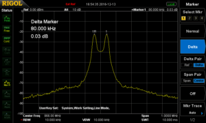
Figure 1: 2FSK Signal with FSK deviation of 40 kHz, fcarrier = 866 MHz, tested with DSA832E
The frequency shift of both frequencies is 80 kHz:
- fmax = fcarrier +Δf = 866 MHz + 40kHz
- fmin = fcarrier – Δf = 866 MHz – 40kHz
- fmax – fmin = 80kHz
Frequency shift is 2 x FSK deviation: - Δ(f2-f1) = 2 x Δf
In constellation diagram of a 2FSK signal is visible in figure 2.
The tests performed in figure 3 and figure 4 show different kind of important measurement: - Signal shall not be higher than customer defined pass / fail curve (see figure 3). Test can be performed with a DSA832, DSA832E or DSA875.
- Absolute power values of these two frequencies can be analysed (figure 4, marker 2R and 3D)
- Information of carrier offset can be checked with marker function (figure 4, marker 1D)
- Difference of power values of two frequencies can be measured (figure 4, marker 2R and 2D)
Another measurement is the analysis of occupied bandwidth (OCP). OCP measures the frequency range which contains 99% of spectral power of signal. The carrier frequency is centered in the middle of this frequency range (see figure 5). OCP can be measured with DSA800 with the option DSA800-AMK.
Calculation of OCP for 2FSK is defined as follow: - OCPBW6 = Data rate + 2 x Δf
Figure 2: Constellation diagram of 2 FSK, carrier frequency is in the middle
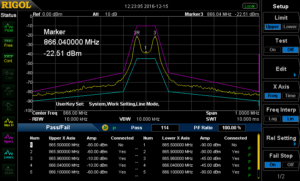
Figure 3: pass / fail mask for curve analysis
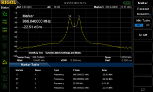
Figure 4: Measurement values of 2FSK signal (see marker table)
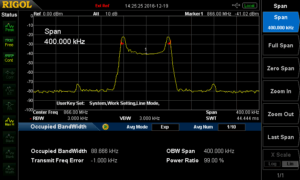
Figure 5: Measurement of occupied bandwidth with a 2FSK signal
4 Speed of DSA832, DSA832E and DSA875 (sweep time of 10 msec: processing time is 30-40 msec.): measure speed of ~50 msec. is possible in normal mode.
5 Following tests can be performed with the option DSA800-AMK: Time Power, Adjacent Channel Power, Channel Power, Occupied Bandwidth, Emission Bandwidth, Signal to Noise Ratio, Harmonic Distortion, Third Order Intercept Point
6 With influence of a roll off factor e.g. with 0.35, OCP will be lower than the calculation.
Example: Data rate: 10kSymbols/sec. and frequency deviation: 40 kHz
- OCPBW = 10 kSymbols/sec. + 2 x 40kHz = 90 kHz
Filtering:
The target of filtering is, that the digital pulses will get a smoother rounded pulse form (according a gauss clock) to get better spectral results and reduce the bandwidth. In RIGOL’s software ULTRA IQ STATION it is possible to select different filter types. A special Gauss Filter for FSK modulation is available to reduce the bandwidth before transmission. Filtering of FSK modulation with that kind of filter results this modulation form into a GFSK modulation. In this software it is possible to adjust the roll off factor (α = B*T), the impulse length (amount of samples per pulse with duration of one bit) and oversampling (additional sampling to be better compliant of sampling theorem to use a simpler reconstruction filter). A gauss characteristic is visible in figure 6. The length of filter is the product of Impulse length and oversampling values. Roll-off factor α is calculated with: - the bandwidth (@-3 dB) of gauss characteristic: B
- the duration of one bit: TBit
2FSK Signal can be generated with Software ULTRA IQ STATION and can be downloaded to an RF signal generator with IQ option (DSG3030-IQ or DSG3060-IQ7).
The clock frequency in the generator will set the wavetable output clock rate. This clock frequency will be calculated from oversampling value and symbol rate (One symbol contains one bit in this 2FSK modulation example).
Clock frequency = oversampling value * symbol rate
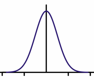
Figure 6: Gauss characteristic
Software S1220 for 2FSK demodulation
DSG3030-IQ: 9 kHz to 3 GHz; DSG3060-IQ: 9 kHz to 6 GHz; IQ Modulator is an Option and contains also external analogue I and Q in-, and outputs
RIGOL provides (option) a demodulation software solution for ASK / FSK demodulation with software S1220. This software works with spectrum analyser DSA832, DSA832E and DSA8758. ASK demodulation will be described at the end of this document.
- This software displays the symbol waveforms of modulation
- Eye diagram can be analysed. This is important to see to analyse jitter effects.
- Specific pattern can be set as reference. Each time the pattern will be transmitted, it will be marked in yellow.
- Carrier Power, Frequency deviation and Carrier frequency offset will be measured.
- Manchester encoding is supported.
- Load and save configuration data
FSK Measurement with DSA815 / DSA705 / DSA710
Software S1220 is usable for
DSA832(E)/DSA875. The measurement speed of
DSA815 / DSA705 and DSA710 is lower than
DSA832(E)/DSA875 and their speed for 2FSK signals are too slow. RIGOL solve this problem with a new option for signal seamless capture (SSC-DSA)9. With the option SSC-DSA 2FSK analysis is also possible to do the FSK measurement with DSA815 / DSA705 and DSA710. With this option the analyser switches into a FFT mode with faster capturing speed. FSK signal measurement (up to three different 2FSK signals) can be performed with that option (see figure 10) in parallel up to 1.5 MHz directly with the device without additional software.
This option has three different main features:
- Real time trace (RT Trace)
- Maximum hold function
- 2FSK signal capture analysis which includes
8 Analyser will be set into a DMA mode (FFT Mode). The analyser can only be controlled with S1220 in DMA mode. 9 This option is only valid for DSA705, DSA710 and
DSA815
o also a maximum hold function parallel to continuous test
o pass/fail measurement according to limit lines to be set
o activation of two mark lines
o measurement of two frequencies from 2FSK signal, amplitude of both frequencies, frequency deviation and carrier offset
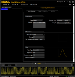
Figure 7: 2FSK Signal generation with ULTRA IQ STATION
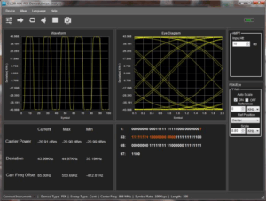
Figure 8: Software S1220 for ASK / FSK demodulation
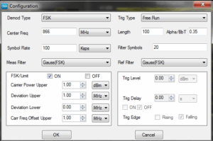
Figure 9: FSK configuration in S1220
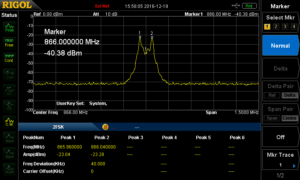
Figure 10: 2FSK measurement with DSA815 and SSC option
ASK – Amplitude Shift Keying
ASK is also a digital modulation form used in e.g. keyless entry or radio beacon in navigation. In simplest form, the characters one “1” and “0” of digital signal will be multiplied with a carrier frequency (see figure 12 to figure 14). On/Off Keying is used in keyless entry systems using ASK modulation.
On/Off Keying (OOK):
- Carrier will be on with “1”; carrier will be off with “0”.
- ASK modulation is 100% (see figure 14) ASK can also be transmitted with a constant carrier. In this case zero “0” will be transmitted with a lower frequency than one “1”. ASK modulation could be e.g. 10% (e.g. for near field communication [NFC] with a bit rate of 424 kbps).
ASK modulation index will be calculated as follow: - m = (A-B)/(A+B) * 100
- If m = 8-14% then ASK modulation is ~10%.
- Modulation depth is B/A
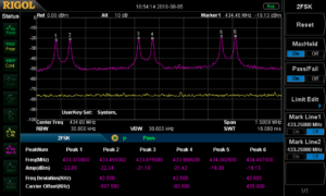
Figure 11: 2FSK measurement with three parallel 2 FSK signals with max hold measurement
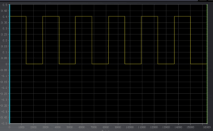
Figure 12: Pulse train with “1” and “0” (digital signal)
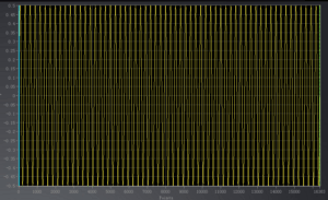
Figure 13: Carrier of ASK (sine signal))
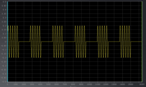
Figure 14: ASK modulation (digital signal * carrier)
ASK bandwidth is defined with:
- B = 2 x Symbol Rate
ASK signals can also be generated in RF signal generator DSG3000-IQ (e.g. DSG3060) together with software ULTRA IQ STATION (see figure 16).
The frequency range is visible in figure 17. ASK Spectrum shows the bandwidth of 2 x sample rate. This spectrum is visible with different signal lines. This makes sense because the expectation of spectrum is not only an on/off cw signal of this modulation form. - A pulse in time range is a SI (sinx/x) function in frequency range.
- A (constant 0101..) pulse train in time range is a SI function multiplied with a dirac train (like a train of pulses with very small pulse width) in frequency range.
- The multiplication with a carrier results into a shift of this function to the frequency of carrier.
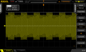
Figure 15: ASK modulation of 10%
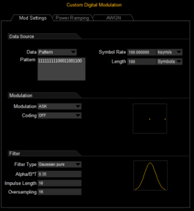
Figure 16: ULTRA IQ STATION settings for ASK generation
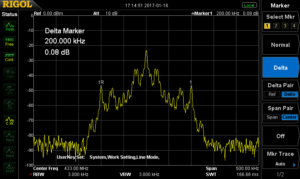
Figure 17: Spectrum of ASK
Digital Signal is visible in zero span mode (see figure 18). The pulse train in time range can be analysed in this mode.
ASK signal can also be analysed with RIGOL’s S1220 ASK-FSK demodulation software. Settings and analysis form are the same like for 2FSK analysis.
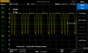
Figure 18: Zero Span analysis of ASK Signal
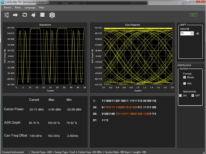
Figure 19: S1220
Products Mentioned In This Article: