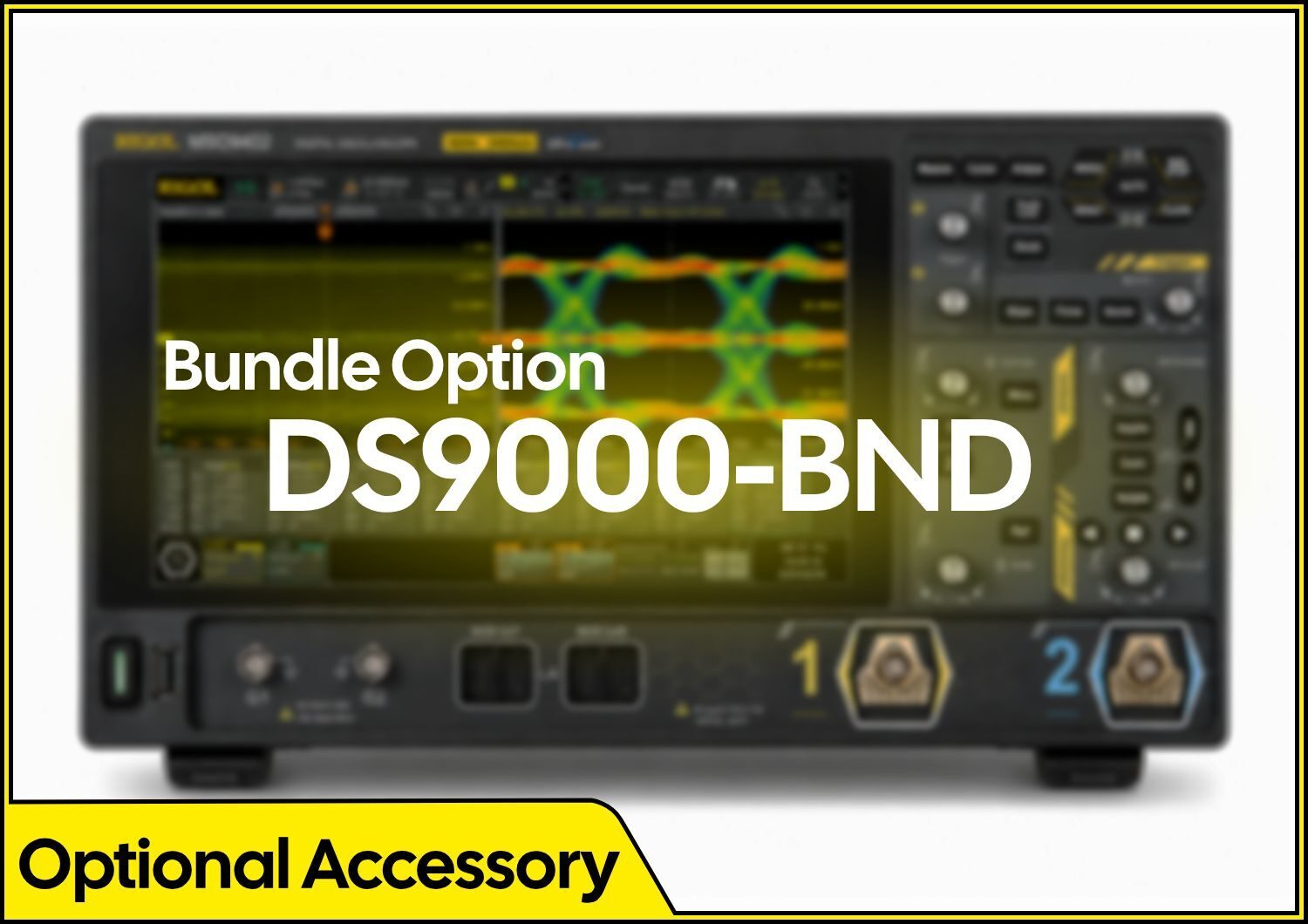
DS80000-JITTA Jitter & Eye Analysis Software Option for DS80000

(£ inc VAT)

Available on back-order, delivery normally 1 - 2 weeks

Availability: Stock models delivered next working day (UK only) for orders placed before 16:30 (Mon - Fri)

SKU: DS80000-JITTA Categories: , , Brand:

Description


DS80000-JITTA Jitter & Eye Analysis Software Option for DS80000

Advanced Eye Diagram and Jitter Analysis Option

Please see the “Specifications” Tab for further information on this software option.

Waveform Analysis

Real-time Eye Diagram (Option)

DescriptionMakes measurements for the clock or data signal over time, analyzes the variance of the technical specifications.
SourceAny analog channel
Clock RecoveryClock recovery for software, constant clock, first-order PLL, second-order PLL, and explicit clock
TypeFully automatic, semi automatic, and manual
Eye Measurement Itemeye one level, zero level, eye height, eye width, eye amplitude, crossing percentage, Q Factor, extinction ration, DCD (duty cycle distortion), rise time, fall time, bit rate, etc.

Jitter Analysis (Option)

DescriptionMakes measurements for the clock or data signal over time, analyzes the variance of the technical specifications.
SourceAny analog channel
Clock RecoveryConstant, PLL, and Explicit
TypeFully automatic, semi automatic, and manual
Jitter MeasurementTIE, Cycle to Cycle, +Width to +Width, -Width to -Width, Pk_Pk, 6-sigma, and RMS
Jitter AnalysisJitter separation, including TJ (Total Jitter), RJ (Random Jitter), DJ (Deterministic Jitter), PJ (Periodic Jitter), DDJ (Data Dependent Jitter), DCD (Duty Cycle Distortion), ISI (Inter-symbol interference), and BR (Bit Ratio). Jitter analysis source: TIE, Cycle to Cycle, +Width to +Width, and -Width to -Width
Measurement DisplayTrend, Spectrum, Histogram, and BathCurve

Search & Navigation

Search, Navigation, and Table

TypeEdge, Pulse
SourceAnalog channel
CopyCopies the search settings from or to the trigger settings mutually, including threshold setting and search condition settings
Result DisplayDisplays the result in the form of the mark table in the multi-pane window. The search results such as the time, pulse width, data, and address of each event can be exported to the external storage device or internal memory as a file suffixed with “.csv”.
NavigationTime navigation: navigates to view the acquired waveforms in time order.
Event navigation: uses the navigation keys to scroll through the event search results and navigates to the specified event.

Serial Decoding

Number of DecodingsFour protocol types can be decoded and enabled at the same time
Decoding TypeStandard: GPIO
Option: RS232/UART, I2C, SPI, CAN, CAN-FD, FlexRay, LIN, I2S, MIL-STD-1553, USB2.0
GPIOUp to 4 bits of Parallel decoding, supporting any analog channel; supports user-defined clock and auto clock settings.
Source channel: CH1 to CH4
RS232/UART (Option)DS80000-EMBDA option
Decodes the RS232/UART (up to 20 Mb/s) bus’s TX/RX data (5-9 bits), parity (Odd, Even, or None), and stop bits (1-2 bits).
Source channel: CH1 to CH4
I2C (Option)DS80000-EMBDA option
Decodes the address (with or without the R/W bit), data, and ACK of the I2C bus.
Source channel: CH1 to CH4
SPI (Option)DS80000-EMBDA option
Decodes the MISO/MOSI data (4-32 bits) of the SPI bus. CS and Timeout are supported.
I2S (Option)DS80000-AUDIOA option
Triggers on 2’s complement data of audio left channel, right channel, or either channel (=, ≠, >, <, ≥, ≤). The available alignment modes include I2S, LJ, and RJ.
Source channel: CH1 to CH4
MIL-STD-1553 (Option)DS80000-AEROA option
Triggers on Sync (Data Sync, Cmd/Status Sync, and All Sync), Data, RTA +11Bit, and Error (Sync Error and Check Error) of the MIL-STD-1553 bus.
CAN (Option)DS80000-AUTOA option
Triggers on the start of a frame, end of a frame, Remote ID, Overload, Frame ID, Frame Data, Data&ID, Frame Error, Bit Fill, Answer Error, Check Error, Format Error, and Random of the CAN signal (up to 5 Mb/s). The supported CAN bus signal types include CAN_H, CAN_L, TX/RX, and DIFF.
Source channel: CH1 to CH4
FlexRay (Option)DS80000-AUTOA option
Triggers on the specified position (TSS End, FSS_BSS End, FES End, DTS End), frame (null, Sync, Start, All), symbol (CAS/MTS and WUS), error (Head CRC Err, Tail CRC Err, Decode Err, and Random Err) of the FlexRay signal (up to 10 Mb/s).
Source channel: CH1 to CH4
LIN (Option)DS80000-AUTOA option
Triggers on the Sync, ID, Data (length settable), Data&ID, Wakeup, Sleep, and Error frame of the LIN bus signal (up to 20 Mb/s).
Source channel: CH1 to CH4

Waveform Measurement

Number of Measurements41 auto measurements; and up to 14 measurements can be displayed at a time.
Measurement SourceCH1 to CH4, Math1 to Math4
Measurement ModeNormal (realized by software) and Precision (W); for Precision, only supported by analog channel
Measurement RangeMain, Zoom, Cursor, Full-memory
All MeasurementDisplays 41 measurement items for the current measurement channel; the measurement results are updated continuously; you can switch the measurement channel.
VerticalVmax, Vmin, Vpp, Vtop, Vbase, Vamp, Vupper, Vmid, Vlower, Vavg, VRMS, Per. VRMS, Overshoot, Preshoot, Area, and Period Area.
HorizontalPeriod, Frequency, Rise Time, Fall Time, +Width, -Width, +Duty, -Duty, Positive Pulse Count, Negative Pulse Count, Rising Edge Count, Falling Edge Count, Tvmax, Tvmin, +Slew Rate, and -Slew Rate
OthersDelay(A1-B1), Delay(A1-B1), Delay(A1-B1), Delay(A1-B1), Phase(A1-B1), Phase(A1-B1), Phase(A1-B1), and Phase(A1-B1)
AnalysisFrequency counter, DVM, histogram, zone trigger, eye diagram (option), and jitter analysis (option)
StatisticsItems: Current, Average, Max, Min, Standard Deviation, Count
Max. 1,000 times statistics supported

Waveform Calculation

No. of Math Functions4, 4 math functions available to be displayed at one time
OperationA+B, A-B, A×B, A/B, FFT, A&&B, A||B, A^B, !A, Intg, Diff, Sqrt, Lg, Ln, Exp, Abs, AX+B, LowPass, HighPass, BandPass, and BandStop
Color GradeSupporting FFT
Record LengthMax. 10 Mpts
Window TypeRectangular, Blackman-Harris, Hanning (default), Hamming, Flattop, and Triangle.
Peak SearchA maximum of 15 peaks, determined by the user-defined threshold and offset threshold

Waveform Analysis

Waveform Recording

DescriptionStores the signal under test in segments according to the trigger events, that is, saves all the sampled waveform data as a segment to the RAM for each trigger event. The maximum number of the sampled segments is 2,000,000
SourceAll enabled analog channels
AnalysisSupports playing frame by frame or continuous playing; capable of calculating, measuring, and decoding the played waveforms

Pass/Fail Test

DescriptionCompares the signal under test with the user-defined mask to provide the test results: the number of successful tests, failed tests, and the total number of tests. The pass/fail event can enable immediate stop, beeper, and the screenshot
SourceAny analog channel

Histogram

DescriptionThe waveform histogram provides a group of data, showing the number of times a waveform hits within the defined region range on the screen. The waveform histogram not only shows the distribution of hits but also the ordinary measurement statistics.
SourceAny analog channel
TypeHorizontal and vertical
MeasureSum, Peaks, Max, Min, Pk_Pk, Mean, Mode, Bin width, Sigma, and XScale

Color Grade

DescriptionProvide a dimensional view for color grade waveforms, color grade >16, 256-level color scale display
SourceAny analog channel
Color ThemeTemperature and intensity
ModeSupports all modes

Cursor

Number of Cursors2 pairs of XY cursors
Manual ModeVoltage deviation between cursors (ΔY)
Time deviation between cursors (ΔX)
Reciprocal of ΔX (Hz) (1/ΔX)
Track ModeFix Y-axis to track X-axis waveform point’s voltage and time values
Fix X-axis to track Y-axis waveform point’s voltage and time values
Auto MeasurementAllows to display cursors during auto measurement
XY ModeMeasures the voltage parameters of the corresponding channel waveforms in XY time base mode.
X = Channel 1, Y = Channel 2

Trigger System

Trigger SourceAnalog channel (CH1~CH4), EXT TRIG
Trigger ModeAuto, Normal, Single
Trigger CouplingDC: DC coupling trigger

AC: AC coupling trigger

High Frequency Rejection (Low Pass Filter): High frequency rejection, cut-off frequency~75 kHz (internal trigger only)

High Frequency Rejection (High Pass Filter): Low frequency rejection, cut-off frequency~75 kHz (internal trigger only)

Noise RejectionIncreases delay for the trigger circuit (internal trigger only), On/Off
Trigger BandwidthInternal Trigger: Analog Bandwidth

External Trigger: 200 MHz

Trigger SensitivityInternal Trigger: 3 div, ≤ 2 mV/div; 1.5 div, 2 mV/div to 5 mV/div; 1 div, 5 mV/div to 50 mV/div; 0.5 div, ≥ 50 mV/div; 0.75 div or 0.8 div, @500mV/div

External Trigger: 500 mVpp (DC to 200 MHz)

EXT TRIGInput Impedance: 1 MΩ ± 1%, SMA connector

Trigger Jitter (Typical): ≤1 nsrms
Normal acquisition, Edge trigger, trigger level located near 50% of EXT input signal

Trigger Level RangeInternal Trigger: ± 5 div from the center of the screen

External Trigger: ±4 V

Trigger Type

Trigger TypeStandard: Edge trigger, Pulse trigger, Slope trigger, Video trigger, Pattern trigger, Duration trigger, Timeout trigger, Runt trigger, Window trigger, Delay trigger, Setup/Hold trigger, Nth Edge trigger
Option: RS232/UART, I2C, SPI, CAN, FlexRay, LIN, I2S, and MIL-STD-1553
EdgeTriggers on the threshold of the specified edge of the input signal. The types can be Rising, Falling, or Either
Source channel: CH1 to CH4, or EXT
PulseTriggers on the positive or negative pulse with a specified width. The pulse width is greater or smaller than a certain value or within a certain time range.
Source channel: CH1 to CH4
SlopeTriggers on the positive or negative slope of the specified time. The slew time is greater or smaller than a certain value or within a certain time range (200 ps to 10 s).
Source channel: CH1 to CH4
VideoTriggers on all lines, specified line, add field, or even field that conforms to the video standards. The supported video standards include NTSC, PAL/SECAM, 480p/60Hz, 576p/50Hz, 720p/60Hz, 720p/50Hz, 720p/30Hz, 720p/25Hz, 720p/24Hz, 1080p/60Hz, 1080p/50Hz, 1080p/30Hz, 1080p/25Hz, 1080p/24Hz, 1080i/60Hz, and 1080i/50Hz
Source channel: CH1 to CH4
PatternIdentifies a trigger condition by searching for a specified pattern. The pattern is a combination of multiple selected channel sources. The logic pattern of each channel is H, L, X, Rising, and Falling
Source channel: CH1 to CH4
DurationTriggers when the specified pattern meets the specified duration condition. The pattern is a combination of multiple selected channel sources. The logic pattern of each channel is H, L, and X. The duration is greater or smaller than a certain value, or within a certain time range, or outside a certain time range.
Source channel: CH1 to CH4
TimeoutTriggers when duration of a certain event exceeds the specified time (200 ps to 10 s). The event can be specified as Rising, Falling, or Either.
Source channel: CH1 to CH4
RuntTriggers when the pulses pass through one threshold but fail to pass through another threshold.
Source channel: CH1 to CH4
WindowTriggers in a specified window state when the rising edge of the signal crosses the upper threshold or the falling edge crosses the lower threshold. The window state can be Enter, Exit, or Time.
Source channel: CH1 to CH4
DelayTriggers when the time difference between the specified edges of Source A and Source B meets the preset time. Delay is greater or smaller than a certain value, or within a certain time range, or outside a certain time range.
Source channel: CH1 to CH4
Setup/HoldWhen the setup time or hold time between the input clock signal and the data signal is smaller than the specified time (200 ps to 10 s).
Source channel: CH1 to CH4
Nth EdgeTriggers on the Nth edge that appears after the specified idle time. The edge can be specified as Rising or Falling.
Source channel: CH1 to CH4

Reviews

There are no reviews yet.

Only logged in customers who have purchased this product may leave a review.